Ground Control: Front Installation


Disclaimer:
This procedure is meant to be a reference on the removal and replacement of the front struts and coils. If you read past this paragraph and you decide to apply anything that is contained within this reference you are assuming total responsibility and liability for your actions including but not limited to damage to your or someone else's vehicle or person.

It's important that you know your mechanic abilities. If you feel that this is over your head, don't do it -- get a professional to do it.


Prep work:
Record the ride height at all four wheels. Measuring from the center of the wheel vertically to the top of the fender arch, my 2000 Z3 2.8 was at 14.5" on all four corners. The Bentley manual suggests measuring from the edge of the rim at the bottom of the arc to the top of the fender arch; you can use either method -- just be consistent.

Make sure you have the needed tools at hand:

  • 3/8" drive metric socket set with various extensions
  • 1/2" drive metric socket set with various extensions
  • Torque wrench (10-80 ft/lbs will work)
  • Metric open-end wrenches
  • Hydraulic floorjack
  • Jackstands (2)
  • Gloves are nice to have
Lifting the car:
Chock the rear wheels.

Using a floorjack on the cross-member towards the front of the car, carefully lift the car until you can place jackstands under both front jack points (just behind the front wheels). If the floorjack is too tall to fit under the car you can use the tirejack to lift one side slightly first.

Lower the car gently onto the jackstands

Remove the wheel (17mm)

Disassembly (per side):
Use the floorjack to support the front steering-arm assembly.

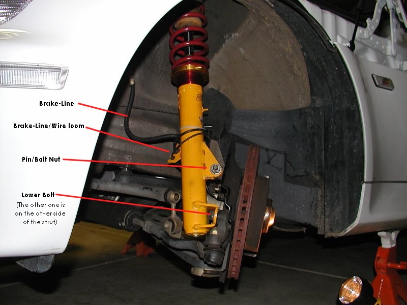
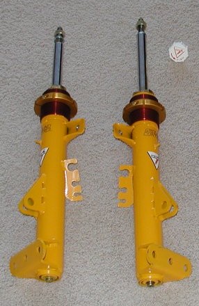
Study the photo to the right. It was taken with the new strut already installed, but it works for reference purposes.

Remove the brake-line, abs-brake sensor lead, and brake-wear indicator lead (one side only) from the loom on the backside of the strut. I didn't need to disconnect anything.

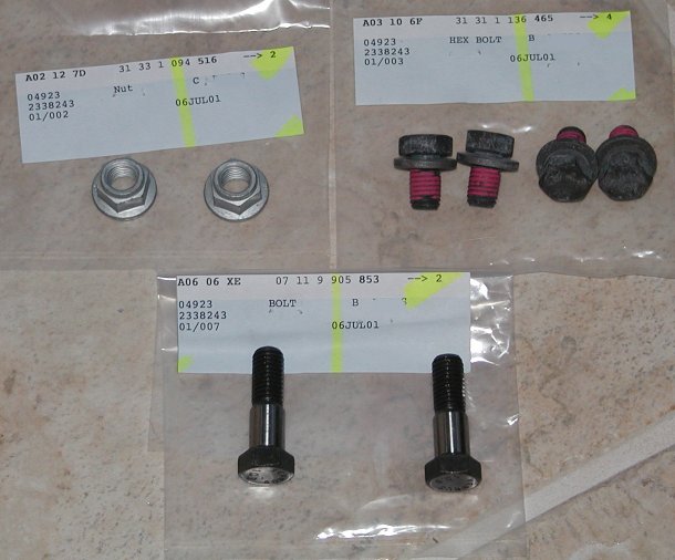
Using a 18mm socket, remove the two bolts securing lower end of the steering arm assembly to the strut. NOTE: you can benefit greatly by turning the wheel to get a good shot at nuts and bolts. If the ignition is unlocked, you can just grab the brake-disc and twist. NOTE: 18mm is an 'odd' size for METRIC and your set may not have that size. You will want a socket with a 1/2" drive; a couple extensions help, as will a breaker bar or impact wrench.

Using a 18mm socket and wrench, remove the NUT from the bolt securing the top of the steering arm assembly to the strut (leave the bolt in place now, it acts as a pin). I believe both the nut and the bolt head are 18mm.

Using some heavy wire or cord (I used 14g wire), secure the steering arm assembly so it will not fall/flop when you remove the remaining pin/bolt.

Place the floorjack under the end of the steering arm assembly to help support it (do not lift!).

Using a 13mm socket, remove the 3 (per side) flange nuts holding the top of the struts. The only thing holding the strut in place now is that last pin/bolt.

Remove the pin/bolt and wiggle the steering arm assembly free from the strut. The strut is heavy, so you may want help here to hold/secure the steering arm assembly (as needed).

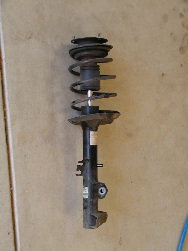
Lower the strut enough that the top end can be swung out from under the fender.

Lift the strut out being careful not to snag the brake line and sensor wire(s). You will be putting the new strut back in the same way, so note how it came out from between the brake line and wire(s).


This is pretty much all that holds your front wheels to the car! The red coating on the short bolts is a self-lock coating. It's important to replace the bolts with new ones (as shown) when reinstalling the front struts. The longer, shanked bolt and the flange nuts secure the upper end of the steering-arm assembly to the strut.


Parts Familiarization:
The stock strut assembly (this is what you should have just removed):

Replacement options:

  • Partial replacement #1: This option provides a new strut housing, cartridge and coil. The only parts from the stock strut that you will re-use are the top strut mount and bump stop. This is the option I chose.
  • Partial replacement #2: This option re-uses your stock strut housing, replacing the inner cartridge and probably the coil. This would require disassembly of the stock unit. The stock housing must be cut open and the new cartidge swapped for the old one.
  • Full replacement: You may be able to find a complete replacement strut. This would include the housing, cartridge, coil, and top strut-mount pre-assembled.

New Parts:
  • Eibach coil with upper seat (temporarily zip-tied to the top of the coil)
  • Washer (not pictured, fits between the upper seat and the upper strut mount)
  • GC Strut housing with Koni cartridge (yellow)
  • Ride-height adjuster and coil seat (red and gold)
Note the part number on the coil (GC180.64.44). This is a special part made by Eibach for Ground Control. The part number indicates a spring-rate of 180mm length, 64mm inside-diameter, 44 spring-rate (Newton meters -- multiply by about 5.7 to get 250). The 180mm length ended up being too short for my car (ride-height was too low), so I exchanged the coils for the 200mm long version.

Note the two tabs just below the red sleeves on the struts. This is the anti-rollbar mount for M-Roadsters/M-Coupes. Ground Control built the housing like this for my Z3, so I can use anti-roll bars designed for these cars (though I can still use the stock unit if desired).

If your struts have these tabs then there is a LEFT and a RIGHT; otherwise they are interchangeable. The new struts will be installed with the tabs aiming towards the rear of the car.

Strut Disassembly:
Disassembling the strut is a potentially dangerous procedure! The coil is under great compression and must be carefully dealt with. Proper tools and procedures must be used to avoid severe injury.

I highly recommend taking the complete strut assembly to a mechanics shop for disassembly. You should be able to find a place that can do it while you wait for about $20.

Strut Assembly:
Assembling the new strut is far less exciting than disassembly, though there are some tricks involved. With the strut shaft fully extended, the new coil should not be under any compression. This assumes you are installed something like an Ground Control/Eibach coil.
  • Slide the coil over the top of the strut shaft and onto the seat.

  • Slide the upper seat and washer over onto the strut shaft.

  • Slide the upper strut mount (from the old strut) onto the strut shaft.

  • Slide the supplied washer onto the strut shaft and thread on the nut.

  • Tricky part: Torque the top nut. This is pretty tough because the strut shaft will spin. There's a special tool that can be used to hold the shaft while tightening the nut, or you can use an air-impact wrench on a low-setting to do this. Do NOT grab the strut-shaft with anything that could possibly score or scratch the polished surface.
Strut Re-installation:
Installation is real easy, just remember that the sway-bar mount tabs (if your strut housing have them) aim toward the rear of the car. Still, it helps to have a second pair of hands to help hold the steering-arm assembly in place, and to thread on the upper strut mount nuts while you're supporting it from below.

Lower the strut into position (bottom-end first) far enough that you can swing the top-end under the fender. Once clear, raise the strut until the upper-mount bolts go through the holes; loosely thread on one or two of the nuts.

Verify that the brake line, ABS sensor wire and brake-liner sensor wire (only on one side) are routed correctly; compare to the other side if needed. Thread the brake line and wires onto the loom (welded onto the strut).

Wrestle the steering-arm assembly into place against the strut. This may require some effort and patience. I found it easiest to get the top connection point lined up first. A large screwdriver or center-punch can be used to help get the holes aligned. Once aligned, insert the pin/bolt so the head of the bolt is towards the rear of the car; loosely thread on the flange nut.

The two lower holes may not be perfectly aligned as the steering-arm assembly is still free to twist away. Make sure the flange on the strut is flush against the steering-arm before attempting to thread in the bolts. Once everything is lined-up, carefully thread in the bolts being careful not to cross-thread them.

Move the steering lock-to-lock verifying that the brake-line and sensor wires are not stretched or pinched at any point of travel.

Torque all the hardware:

  • Lower steering-arm to strut bolts (2)
  • Upper steering-arm to strut bolt and nut
  • Upper strut-mount to chassis nuts (3)

The stock strut housing has a stud onto which a wire clip is attached. Ground-Control also provides a stud, but in my case it was too high on the strut and the stud diameter was too small. To resolve this, I simply used a large zip-tie (wire-tie) to hold it in the correct position.


Questions or Comments
Back to Dave's Bimmer page
This page was retrieved from archive.org January 2009 because Dave's site is gone

Esmerelda's Page Esmerelda's Home Page~ Z3ers.com
© Rachel Corey Katz all rights reserved